Narrow-linewidth and frequency-stable cw lasers are nowadays key components in reaching high performances in many domains and applications where the laser interferometry process is involved, like for LiDAR, SENSING, METROLOGY, QUANTUM TECHNOLOGIES, …. Making a narrow-linewidth laser that is frequency stable most of the time is achieved by the active frequency stabilization of the laser emission frequency.
As we describe in another article, a laser does not exhibit a “pure” emission frequency. The laser emission frequency is not an ideal sine wave in the time domain and not a delta Dirac function in the frequency domain. The laser emission frequency fluctuates over time, with different amplitudes at different time scales, which gives it a linewidth and a given frequency stability.
One of the possible solutions to reach this is through active frequency stabilization, and this is what is discussed in this article.
LASER FREQUENCY STABILIZATION: MAIN CONCEPT
The frequency stabilization of continuous-wave lasers is an active process that aims to reduce the frequency fluctuations at different time scales. This process needs only 3 major elements that are
- A Discriminator in order to get in real time the Frequency (or the phase) fluctuations of the laser,
- A Servo Controller in order to adapt the electrical signal and close the locking loop, and
- An Actuator in order to act on the laser emission frequency.
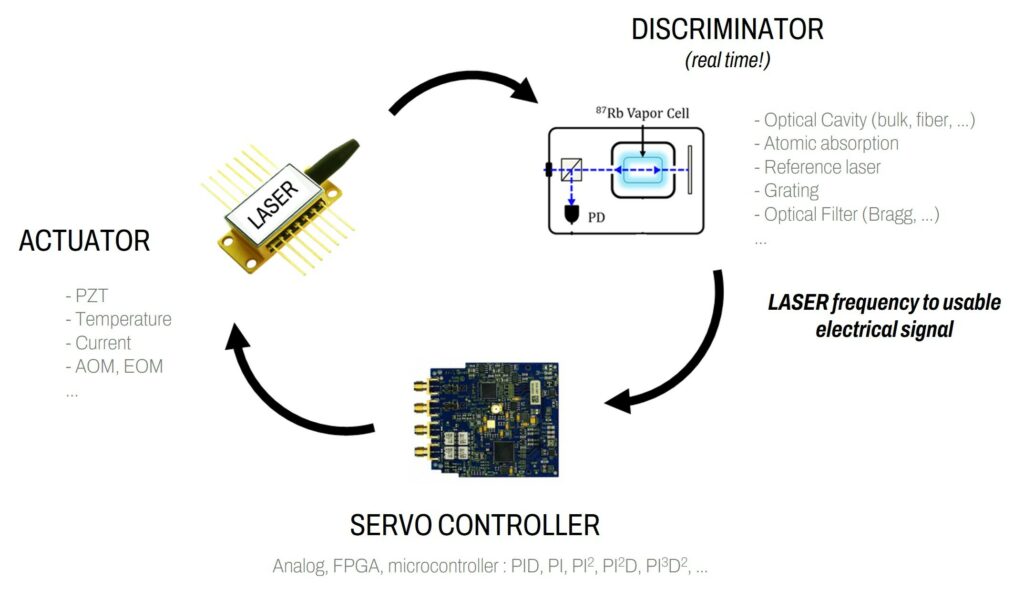
 The Discriminator
The Discriminator is a device that gives in real time (this is essential) an electrical signal that is proportional to the laser frequency/phase fluctuations, over a given bandwidth. So, this is a “DC-coupled” device. The main characteristics of this device are the following:
- Detection bandwidth (in Hz)
- Conversion factor (in V/Hz or V/nm or V/rad)
Other parameters are also important to take into account like:
- Detection Noise floor (in Hz²/Hz for example),
- Maximum optical power (in mW)
- Working range (in nm)
- Polarization compatibility, connectivity (free-space, fiber-coupled, …)
- Sensitivity to the environment (vibration, acoustics, temperature, …)
- Size and cost, of course
In terms of possible Discriminators, we can list (non-exhaustively) the following:
- Optical Cavity (bulk, fiber) with or without a Pound–Drever–Hall detection, side of fringe, …
- Atomic Absorption
- Reference laser by beating and demodulation
- Optical Grating
- Optical Filter (Bragg, …)
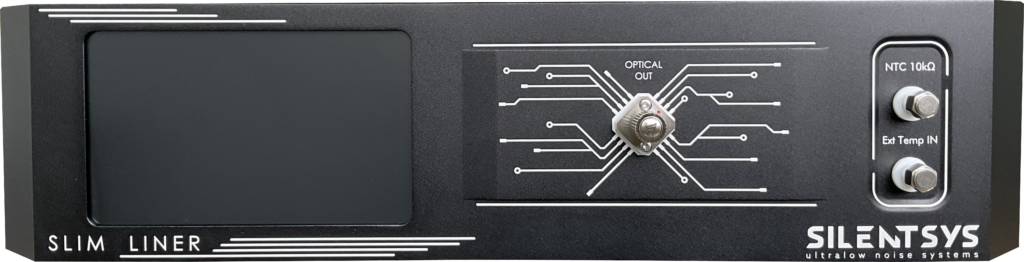
Alternatively, a Fiber Interferometer like what SILENTSYS develops can be used and that is presented in this article.
 The Servo Controller
The Servo Controller is the key control electronic that closes the locking loop and that adapts the signal from the Discriminator for the Actuator. This element needs to be tuned depending on the setup to reach the best performances. The main characteristics are the following:
- Input voltage noise (in V/√Hz)
- Response time / Bandwidth (in s or Hz)
- Open-loop gain (in dB)
- Functionalities (Proportional gain, Integrator, Derivative gain, …)
- Input/Output voltage range (in V)
- Size and cost, of course
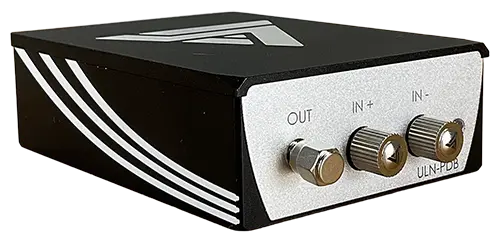
For this element, SILENTSYS proposes a versatile and performant solution, accessible here.
The Actuator
The Actuator is the last main element of this process and most of the time the trickiest one. It is an element in or outside of the laser cavity that can change the laser frequency. The main characteristics are the following:
- Modulation range (in Hz or nm)
- Modulation bandwidth (in Hz)
- Conversion factor (in Hz/V)
Typically, the laser frequency actuators are (non-exhaustively) the following:
- Intracavity PZT (enables a laser cavity length change: usually slow (kHz bandwidth) but important range (few GHz or more))
- Temperature (enables also a laser cavity length change but much slower with much wider range)
- Driving current (for example, for Semiconductor Laser Diode like DFB or DBR, shows both good bandwidth (MHz level usually) and wide range (GHz level))
- Intracavity EOM (Electro-Optic Modulator) (enables laser frequency change by optical cavity change thanks to refractive index tuning, which shows very fast modulation (GHz level) but with limited range (depends on the cavity length))
- External AOM (Acousto-Optic Modulator) (shows good bandwidth (MHz level) but low range (few MHz))
In fact, the goal is in general to reduce as much as possible the frequency fluctuations and as fast as possible. The following figure shows what happens to the Frequency Noise spectrum when the laser is free-running (no active frequency stabilization) and when it is locked. As we can see, the frequency noise reduction starts close to 1 MHz with what is called the “servo bump” with an increase of the noise compared to the free-running regime. This bump can be reduced and there is a compromise between it and the noise reduction at lower Fourier frequencies as presented in this article. After this servo bump, the locked case shows an important noise reduction that depends on the Discriminator, Servo Controller, and Actuator characteristics. It is important to mention that only the frequency fluctuations that can be detected and changed can be corrected!

LASER FREQUENCY STABILIZATION: POSSIBLE CONFIGURATIONS
Usually, the common locking configuration is the scheme presented at the beginning of this article, i.e., the Feedback method. We can list here three different locking methods:
- Feedback: real time detection + active correction at the source
- Feedforward: real time detection + active compensation
- Semi-Feedback: real time detection + active correction after the source
Feedback Configuration

For the Feedback method, the pros and cons are the following:
- Robust
- For “any” type of fluctuations/noise
- Easy to set up
- Needs a good laser actuator
- Limited bandwidth (total loop delay)
- Can oscillate
Feedforward Configuration

For the Feedforward method, the pros and cons are the following:
- Very high bandwidth by fine delay tuning
- Fast fluctuations corrections
- Hard to reach a perfect compensation
- Not really robust in time
- Not converging
Semi-Feedback Configuration

For the Semi-Feed method, the pros and cons are the following:
- Can correct fast fluctuations with fast frequency actuator
- Easy to set up
- Can oscillate
- Robust but not as Feedback (depends on the frequency actuator range, but robust if a slow lock option is engaged)