Narrow-linewidth and frequency-stable cw lasers are nowadays key components in reaching high performances in many domains and applications where the laser interferometry process is involved, like for LiDAR, SENSING, METROLOGY, QUANTUM TECHNOLOGIES, …. Making a narrow-linewidth laser that is frequency stable most of the time is achieved by the active frequency stabilization of the laser emission frequency.
As we describe in other articles, a laser does not exhibit a “pure” emission frequency. The laser emission frequency is not an ideal sine wave in the time domain and not a delta Dirac function in the frequency domain. The laser emission frequency fluctuates over time, with different amplitudes at different time scales, which gives it a linewidth and a given frequency stability.
One of the possible solutions to this is active frequency stabilization. In order to do so, it is important to correctly adjust the Servo Controller parameter values.
Moreover, a Servo Controller can be used in any active stabilization loop, not only to stabilize laser emission frequency. It could be also laser emission intensity, phase of RF signal, ….
SERVO CONTROLLER: MAIN CONCEPT
The frequency stabilization of continuous-wave lasers is an active process that aims to reduce the frequency fluctuations at different time scales. This process needs only 3 major elements:
- A Discriminator in order to get in real time the Frequency (or the phase) fluctuations of the laser
- A Servo Controller in order to adapt the electrical signal and close the locking loop
- An Actuator in order to act on the laser emission frequency
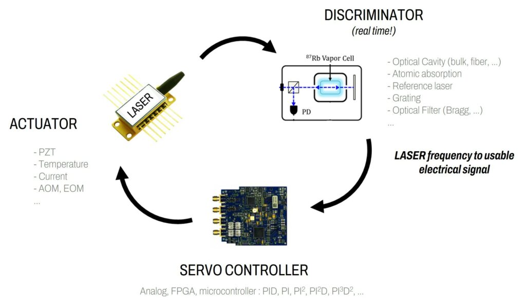
The Servo Controller is the key control electronic that closes the locking loop and adapts the signal from the Discriminator for the Actuator. This element needs to be tuned depending on the setup to reach the best performances. The main characteristics are the following:
- Input voltage noise (in V/√Hz)
- Response time / Bandwidth (in s or Hz)
- Open-loop gain (in dB)
- Functionalities (Proportional gain, Integrator, Derivative gain…)
- Input/Output voltage range (in V)
- Size and cost, of course
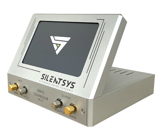
For this element, SILENTSYS proposes a versatile and performant solution, accessible here.
The role of this electronic board is to minimize the input signal by acting on its output. We can simply see it as an active electronic filter where we adjust the gain and the phase to improve the locking.
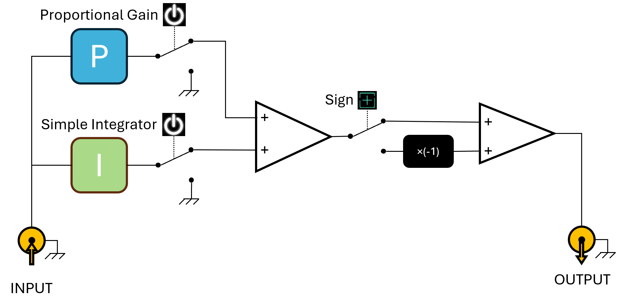
A servo controller can be either analog or digital and can propose a few functionalities depending on the need. The Servo Controller we usually use here at SILENTSYS has a Proportional gain (P) and a Simple Integrator (I). The transfer function (Output Voltage divided by the Input Voltage) is shown in the next figure. The Input signal is also commonly called “Error Signal” and the goal is to minimize the error.
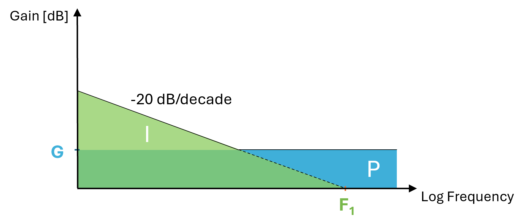
In this case, we can link the output voltage to the input voltage like this:
OUTPUT(t) = SIGN() [G*INPUT(t) + F INPUT(t)*dt]
First of all, the sign is the main parameter to choose, so positive or negative. With a feedback loop, when closed, the input signal has to be minimized, so it needs to converge and not to exponentially grow. Simply, to lock a system, we need to act on the physical quantity that we want to lock with a signal with an opposite sign in order to compensate for it.
Then, let’s look at the two main gain parameters: Proportional & Simple Integrator.
 Proportional Gain
The role of the proportional gain, because it is a “flat gain”, is to correct mainly the “fast” fluctuations. However, it has not enough gain at low frequencies (long time scale) to really push the input signal down to 0 V. If the gain is too small, the lock will converge slower to the setpoint (0 V in our case) and with more offset; if the gain is too large, the system will simply oscillate, so not locked.

Simple Integrator
The Integral component of the servo controller aims to push down the offset between the error signal and the setpoint. This, the Proportional gain cannot do. So, in order to achieve this, the simple integrator is adding gain in the loop for the low frequencies. The Simple Integrator is mainly useful to correct the slow fluctuations; even if for the Servo that we commercialize the highest cutoff frequency (F1, so the frequency where the gain is 0 dB) is 10 MHz, sometimes just activating the Simple Integrator (no Proportional gain) is enough to reach a good lock.

SERVO CONTROLLER: EXPERIMENTAL CASE
In a real experiment, like when locking the laser emission frequency as discussed above, these are the steps we recommend:
0/ At the beginning, the signal to look at with an oscilloscope is the “Error Signal”, so the signal at the input of the Servo Controller.
1/ When all the loop is connected, you can engage the Proportional Gain, at the minimum value. At that point, you should see on the oscilloscope a “reaction” on the error signal as shown in the first part of Figure 4.
2/ Then, start to increase the Proportional Gain (G) until the signal oscillates (the trace on the oscilloscope becomes thicker) and reduce the gain to have a value before oscillations (typically 3 dB less). Now, the Proportional Gain is close to be optimized.
Note: if even with the minimum gain the loop starts to oscillate, we recommend adding an electrical attenuator at the input connection to reduce the overall loop gain.
3/ Then, engage the Simple Integrator with the lowest cutoff frequency. You should see that the offset is starting to be reduced. Increase the cutoff frequency until it oscillates and then come back to avoid oscillations.
4/ It is locked! Congratulations!
Now, for fine optimization of the parameters, we recommend looking at the signal in the frequency domain and not the time domain. This view is what we call “In-Loop Measurement”; it gives the information that the signal is correctly locked, so that the physical quantity to be stabilized follows properly the Reference. This is not an “absolute measurement”, called “Out-of-Loop”, that could give you information on the Reference performances. From this In-Loop view, as shown in the next figure, the goal is that the noise is reduced within the locking bandwidth and reaches the measurement noise floor at low frequencies. The locking bandwidth is defined by what we call the “servo bump”, so this is the frequency at which the system oscillates and the noise is increased a bit. The fluctuations are corrected for frequencies below this limit. The fluctuations above this servo bump are not impacted, so it remains the same usually.
Moreover, having the best Servo Controller input voltage noise is crucial because this is the reference voltage on which the error signal will be locked.

In some cases, the stabilization does not hold for a while because the output voltage of the Servo Controller arrives to its edge. It means that the stabilization cannot continue. To avoid it, one solution is to use a physical actuator on which the Servo Controller acts that has a wider working range (for example, using an intracavity PZT instead of the pump current for an External Cavity laser).
However, most of the time there is a tradeoff. A wider working range usually also means a lower speed response….
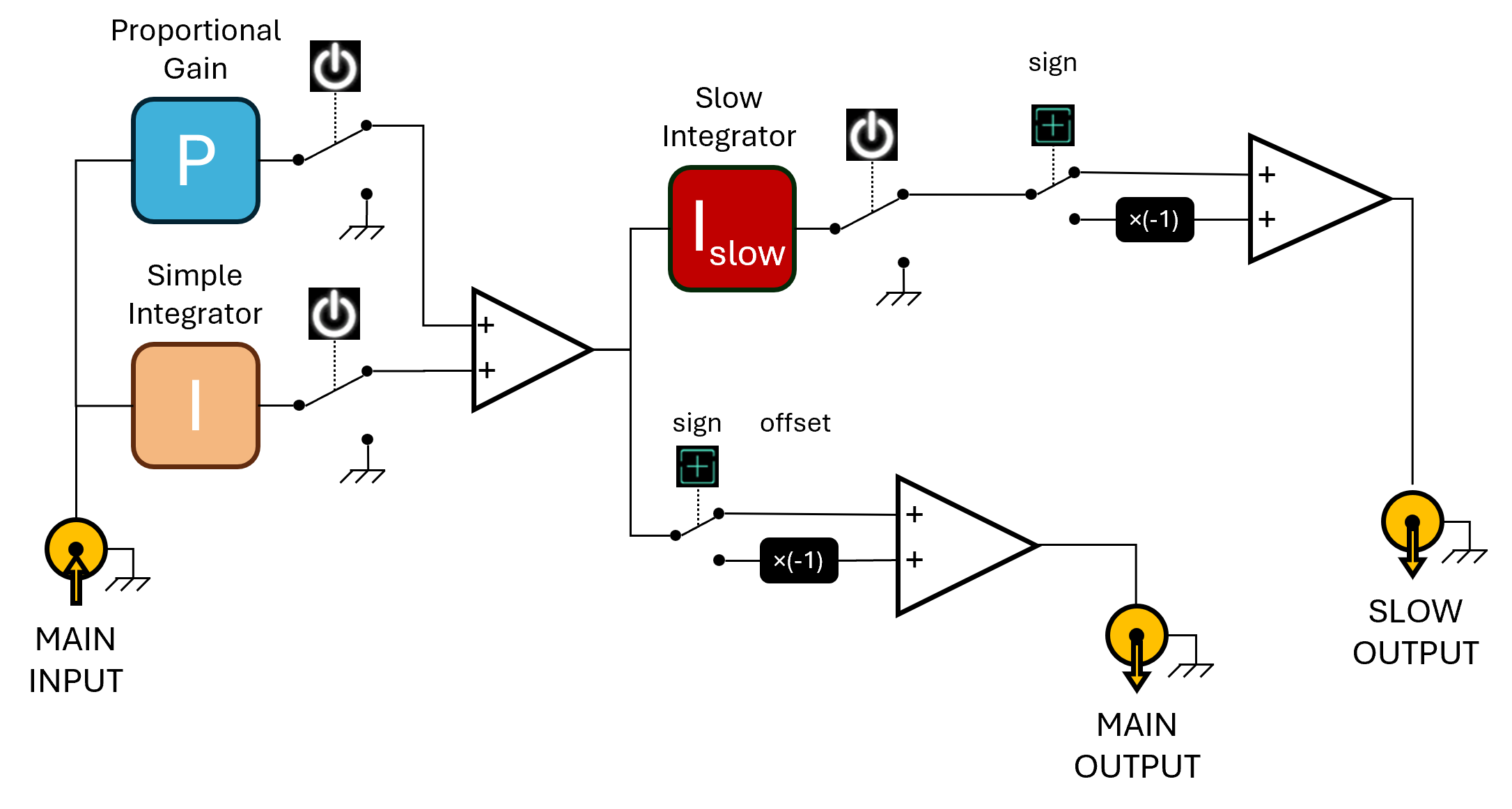
In that case, what is common to do is to use a “Slow lock” that acts on the wider and slower actuator, while the “Fast lock” is maintained. The “error signal” of the “Slow lock” branch is the output of the “Fast lock” branch. So, this is simply possible by using two Servo Controllers in series or by using a device that already has this functionality inside.
This is what we propose with the PID-02 as you can see with the following simplified functional diagram.