Narrow-linewidth and frequency-stable lasers are nowadays key components in reaching high performances in many domains and applications where the laser interferometry process is involved, like for LiDAR, SENSING, METROLOGY, QUANTUM TECHNOLOGIES, …. Making a narrow-linewidth laser that is compact, low cost, and can handle hard environment (temperature, acoustics, vibrations…) is very challenging but not impossible.
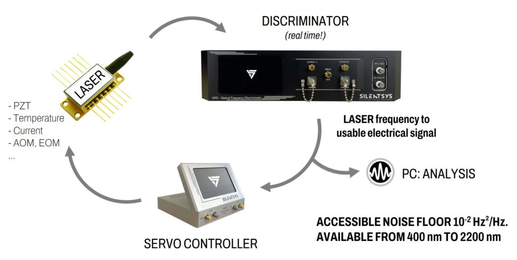
The best way to characterize and stabilize the laser is by being able to detect the laser frequency fluctuations, which is done with an OPTICAL FREQUENCY DISCRIMINATION scheme. At SILENTSYS, we propose a plug-and-play OPTICAL FREQUENCY DISCRIMINATOR (OFD) in order to reach a high-performance laser frequency stabilization/characterization.
We will see here what the main characteristics of an OFD are and how to choose them properly depending on different parameters.
OPTICAL FREQUENCY DISCRIMINATION: DEFINITION
OPTICAL FREQUENCY DISCRIMINATION, or LASER FREQUENCY DISCRIMINATION, is a technique that gives the frequency evolution in the time domain of a single-frequency under-test laser, as we have presented in another article. So, these are methods that convert laser frequency emission into a readable signal, because, in contrast to electronic oscillators, a laser emits an electric field at a very high frequency, typically around 200 THz for telecom lasers (1.5 µm wavelength).
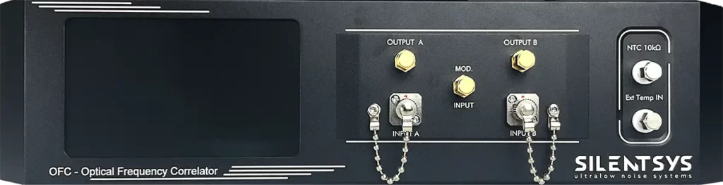
At SILENTSYS, we are also doing OPTICAL FREQUENCY DISCRIMINATION, which is directly integrated in a few of our products like the OFD (Optical Frequency Discriminator) or the OFC (Optical Frequency Correlator). We provide OPTICAL FREQUENCY DISCRIMINATORS that are small, fast, affordable, and available from 400 nm to 2200 nm with a typical working range of 100 nm around the central wavelength.
These are based on modified Michelson or Mach–Zehnder fiber interferometers, with a high vibrations/acoustics isolation, high-level temperature stabilization (at the microkelvin level), and ultralow noise photodetection in order to reach very good laser frequency discrimination precision.
These products make good candidates for laser frequency stabilization or characterization, enabling Frequency Noise PSD measurement, Frequency Stability analysis, and Frequency Noise reduction by more than 60 dB to reach a Hz-level laser linewidth from a MHz one. The frequency stabilization is very easy as there is no need for external laser frequency modulator, complex locking schemes (such as Pound–Drever–Hall), and no need for cavity scanning as with OFD/OFC there is a locking point each half of FSR, so for example each 5 MHz (FSR of 10 MHz) compared to each 1 GHz with a 15 cm long FP cavity.
HOW DOES IT WORK?
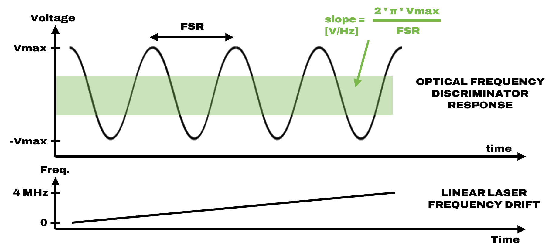
As the SILENTSYS OFD/OFC are based on a modified Michelson or Mach–Zehnder interferometers, so a two-wave interferometric process, the result is a sine fringes pattern against the change of the input laser frequency. At the middle of one fringe (the green zone on the Figure 1), the conversion between the laser frequency fluctuations and the output voltage is linear, so it is then possible to retrieve the laser frequency fluctuations by recording the voltage time trace of the OFD and by knowing 2 important parameters: the amplitude of the fringes (Vmax) and the OFD free spectral range (so the frequency distance between 2 fringes).
In the next figure, as the laser is going through 4 fringes by changing its frequency of 4 MHz, it means that the FSR is 1 MHz in this specific case. The OFD FSR is fixed by construction and can be adjusted between 2 MHz and 2 GHz (other values possible on demand).
HOW TO PROPERLY CHOOSE THE FSR VALUE?
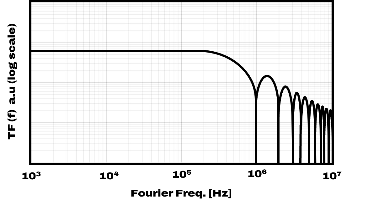
As explained just above, the FSR (Free Spectral Range) is an essential parameter and fixed at the device manufacturing. The FSR defines both the frequency-to-voltage sensitivity (the lower is the FSR, the higher is the sensitivity in V/Hz) and the detection bandwidth.
So, the lower is the FSR, the better it is to be able to measure/stabilize with lower frequency noise floor. But on the other hand, the lower is the FSR, the lower is the measurement/stabilization bandwidth. The −3 dB bandwidth is approx. the FSR divided by 2.
To summarize, it is important for laser frequency stabilization/characterization to be well around the quadrature point, meaning here around 0 V. This is where the conversion is linear. This makes that the laser frequency excursion should be less than approx. FSR/4 to stay in the linear range and have good frequency stabilization/characterization. This avoids non-linearities during the conversion.
In consequence, this implies a huge constraint on the OFD’s FSR regarding the laser frequency noise (linewidth) when it is free-running:
- High laser frequency noise -> High FSR mandatory
- Low laser frequency noise -> Low FSR possible
Usually, the internal rule we have is to set the OFD‘s FSR a minimum 100 times higher than the white frequency noise of the laser (for laser frequency stabilization). For example, for a laser of an instantaneous linewidth of 300 kHz (so a white frequency noise floor of 105 Hz²/Hz), we recommend to not use an FSR below 10 MHz.
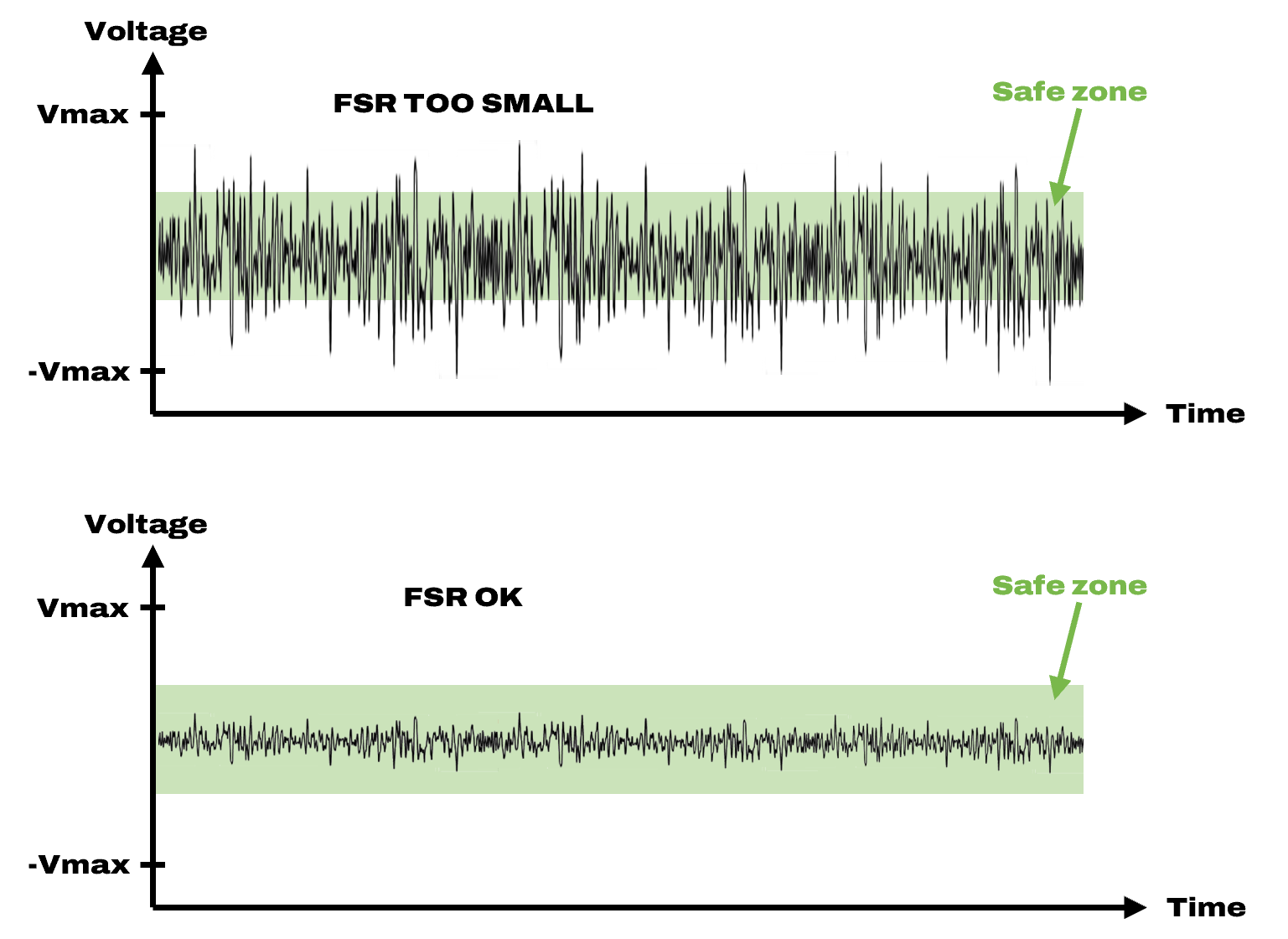
The next figure shows the impact of the white laser frequency noise on the output signal of the OFD for a given FSR. As we can see, while the laser is locked (constantly around 0 V), the frequency noise at high frequencies is not corrected due to being out of the locking bandwidth. If the FSR is too low compared to the thickness of the trace (i.e., the fast laser frequency excursions) this can cause laser frequency jumps (OFD mode-hops) and also increasing of the frequency noise floor due to non-linearities.
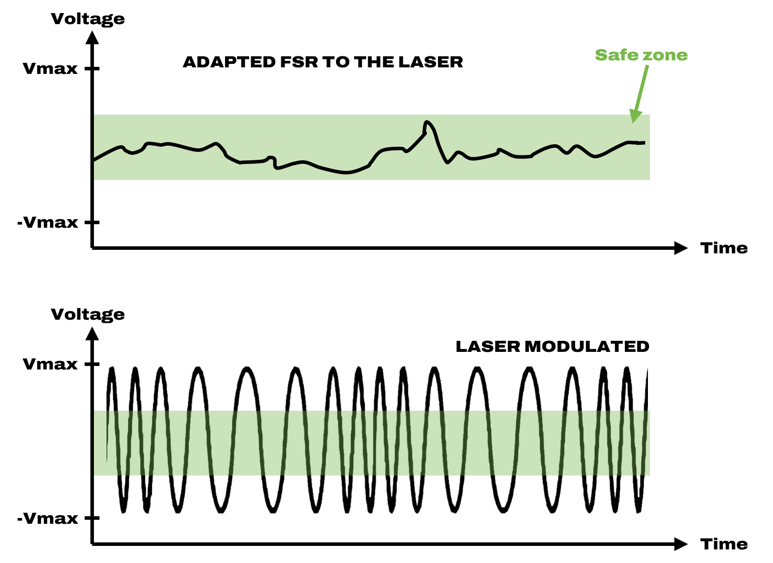
Moreover, if the goal is to evaluate the frequency drift or the frequency noise of a laser that has a high amplitude at “low” frequencies like at the ms range for example, it is important that the laser stays inside the linear conversion range so that the excursion during the measurement is low enough. The next figure shows the result of a frequency-modulated laser and a non-modulated laser. Actually, the modulated laser can just be an ECDL that is very sensitive to the vibration and placed in a wrong environment!
SUMMARY
To conclude this article, here are the typical rules we suggest to correctly choose the OFD’s FSR (few of them need compromises):
- The FSR should equal about 100 times the laser white frequency noise (recommended especially for locking)
- The frequency noise measurement/locking bandwidth is typically the FSR divided by 2 (and FSR divided by 4 for locking)
- The FN-PSD measurement noise floor is improved with lower FSR. Lower sensitivity, relatively, to photodetection noise floor, for example.
- The laser frequency excursions of typ. FSR divided by 4 during the measurement (to stay in the linear conversion range. We recommend even a factor of 10.